While it takes me on average about a month to think up and produce One blog that doesn't bore the pants off someone.
The maestro of the Ham Video VK3YE , writer of a growing Amateur radio book collection, along with his superb website to support his hobby vk3ye.com, has done it again, and now come up with a new challenge a new daily Blog called The Daily Antenna.
The idea is to produce One blog per day on antennas, accessories and related topics.
I don't know how Peter finds the energy and time to fit it all in, but I certainly will be dropping in and reading from time to time, and wish him well with his new venture
I will also drop the link into "My Blog list" on the right handside, because I know it will be a very valuable source of material.
Showing posts with label vk3ye. Show all posts
Showing posts with label vk3ye. Show all posts
Tuesday, 12 February 2019
Sunday, 21 August 2016
Hand-carried QRP antennas VK3YE
The maestro of the Ham video VK3YE has written his 2nd ebook for the kindle. Peter kindly sent me the details as below:


Summary of Hand-carried QRP antennas
Whether through choice or circumstance, more radio
amateurs than ever before are enjoying portable operating.
Suitable equipment is widely available but what about
antennas? Manufactured antennas exist
but only some suit lightweight portable activity. And, it’s easy to overpay for
something that’s too heavy and too lossy for successful QRP.
Hand-carried QRP antennas takes the mystery out
of portable antennas. After inviting
you to assess your needs, it discusses the pros and cons of popular types. Its style is brisk and practical with almost
no maths.
Many ideas for cheap but good materials suitable for
portable antennas are given.
Beginners and those returning to radio after a break should especially
find this section handy.
Finally there’s construction details on a
variety of simple but practical antennas and accessories suitable for
portable operating. All have been built
and tested by the author over almost 30 years of successful QRP activity.
Hand-carried QRP antennas is an ebook readable on
most devices. It’s the author’s second
book, following on from the top-selling Minimum QRP, released in
2015.
ABOUT THE AUTHOR
Peter (mis?)spent his youth at rubbish tips, taking apart
given radios and TVs and building electronic projects that mostly did not
work. He avoided soldering until
figuring out that new solder works better than reusing solder from terminal
strips in valve radios.
Milestones included the construction of a crystal set in
1980, discovering shortwave broadcasting on a valve receiver in 1981 and a
simple ‘electronic organ’ in 1982 from a Dick Smith Fun Way book. Hours were spent putting wires into springs
on a Tandy 150-in-1 electronics set.
Amazingly some wires could be pulled out and the project would still sort
of work with only half the parts in circuit.
Two back to back AM/shortwave radios led to the discovery
of amateur SSB activity and a novice licence in 1985. The following year was spent building
transmitters no one heard. A one valve
crystal controlled CW transmitter from the 1973 ARRL Handbook provided the first
contacts – mostly CW/SSB crossmode on the 3.579 MHz TV colour burst crystal
frequency. The value of frequency
agility was an early lesson and various VFOs were built, most of them
drifty.
The 1990s brought more bands, more modes and smaller
gear. Projects included a 7 MHz VXO CW
direct conversion transceiver, 2m FM portable transceiver, and a 14 MHz CW
transmitter for Cycle 22, then near its peak. Later favourites included HF DSB and SSB
transceivers (often using ceramic resonators, ladder crystal filters, NE602s and
BD139 transistors) and phasing SSB equipment.
Limited space led to experiments with magnetic loops and
HF pedestrian mobile. The joys of the
latter (along with the perils of a trailing counterpoise) were first discovered
with a converted Johnson Viking CB on 28 MHz.
This was mounted in a carpeted chipboard box with battery and 1.5 metre
whip. A move to a bayside suburb brought
further HF portable and pedestrian mobile activity which remains an interest to
this day.

Saturday, 26 March 2016
QSO Today interview with VK3YE
A peruse around the web I came across a recent interview with the multitasking amateur radio constructive video producer VK3YE.
This is well worth a listen, when having your midnight cocoa:
http://www.qsotoday.com/podcasts/vk3ye
I can only reflect some of the similar things of visiting the dump, or being given old televisons & radios to pull apart that got myself interested in the hobby many years ago..
This is well worth a listen, when having your midnight cocoa:
http://www.qsotoday.com/podcasts/vk3ye
I can only reflect some of the similar things of visiting the dump, or being given old televisons & radios to pull apart that got myself interested in the hobby many years ago..
Tuesday, 13 October 2015
Minimum QRP - VK3YE
The Master of the QRP Video, Peter Parker - VK3YE has launched a new ebook for the Kindle titled Minimum QRP.
The book is available for purchase direct from Amazon for a few Pounds, Dollars, or whatever currency your country uses. Just search "Minimum QRP"
The book is written and put over in the simple Peter Parker methodical way, but if you still don't understand the book, don't worry, you can always refer back to his amazing back catalogue of VK3YE video material on his channel. If you like the VK3YE Youtube output buy the book, you will not be disappointed, there is something in it for everyone from the novice to the converted.
 Cover courtesy VK3YE
Further details from the VK3YE Website: http://home.alphalink.com.au/~parkerp/miniqrp.htm
If you don't own a Kindle like myself, this doesn't stop you reading and purchasing. There is a Kindle App available for Android and iPad. Or if you just want to use Windows on your PC to read, there is a Kindle program to download for free from Amazon. App information and download link here for UK users. Once you buy the ebook the file is then downloaded into your Kindle folder.
The book is available for purchase direct from Amazon for a few Pounds, Dollars, or whatever currency your country uses. Just search "Minimum QRP"
The book is written and put over in the simple Peter Parker methodical way, but if you still don't understand the book, don't worry, you can always refer back to his amazing back catalogue of VK3YE video material on his channel. If you like the VK3YE Youtube output buy the book, you will not be disappointed, there is something in it for everyone from the novice to the converted.

Further details from the VK3YE Website: http://home.alphalink.com.au/~parkerp/miniqrp.htm
If you don't own a Kindle like myself, this doesn't stop you reading and purchasing. There is a Kindle App available for Android and iPad. Or if you just want to use Windows on your PC to read, there is a Kindle program to download for free from Amazon. App information and download link here for UK users. Once you buy the ebook the file is then downloaded into your Kindle folder.
Saturday, 18 July 2015
The MDT kit arrives with a sting!
Short form reviewing the MDT kit from Ozqrp a few weeks ago, and then watching the VK3YE Video, gave me the urge to purchase a MDT40 kit. Of course miles are no barrier to this hobby any longer, a quick click and it was in the shopping basket. I coughed up the green ones or Pound notes and sent it over via Paypal.
Less than 10 days later a card dropped through my letterbox. Please pay up? "Unfortunately we can't deliver your item because there is a fee to pay". Meaning it was subject to UK Import Duty of £7.63, plus a £8 Post office charge on top! I really don't mind the Tax, but the Post Office charge of £8, I find this a big no no! A fee for them to handle it and take my money. The Post Office deliver parcels and letters everyday from around the world, and never ask for anymore, until we get into stuff with duty added by customs and then they add this extra sting on top of the bill.
This made the total of the purchase including duty a little over £61. The tax might have taken the icing off the cake, but the kit still represents excellent value for money. Please don't be put off, Ozqrp has done an excellent job of design, and putting this kit together as you will see below:

Post office then satisfied, I walked away with a receipt and the MDT goody box..

The components came well packaged in a sealed box, with all components wrapped in bubble wrap inside.
VK2DOB the owner of Ozqrp has done an excellent job collating all the components together for the MDT, all which have been separated off into little bags and clearly marked. The case comes with pre drilled, clear labelled, front and rear separate panels for the unit, including the hardware and the knobs. Even a Microphone plug has been included in the kit, so you won't have to spend time hunting around or having to go out to purchase one.

A well designed doubled sided PCB, which already has the only SMD component (the varicap diode) soldered to the board . This will save everyone time from fiddling around, especially those like myself with ailing eyesight.

Last night I printed out the manual and bound it up into a simple folder. I recommend everyone print out "all" the 42 pages, and read it from cover to cover a couple of times before starting. Although what may be quite a simple and straight forward process to me, there is still quite a bit for the novice to take in.

The next time I write on this blog I guess certain parts of the kit will be completed? For now, I leave you with two more excellent VK3YE MDT videos, including extra modifications of the unit.
Portable operating with the MDT:
https://www.youtube.com/watch?v=xVvqZlzX8sk
Modifications to the MDT:
https://www.youtube.com/watch?v=rDd4cjkOAi8
Sunday, 28 June 2015
A new 40m DSB kit arrives on the QRP scene
Just when everyone is taking Summer siestas and there seems very little news around to talk about. Along comes a new Direct Conversion 40m Transceiver kit from Australia.
The MDT DSB kit is manufactured by Ozqrp, capable of 2W PEP, it has a full swinging VFO 7.090MHz - 7.130MHz or 7.050MHz - 7.110MHz. A complete kit of components including PCB, and case for $80 (Aus) less than £40 UK plus carriage. Which worked out at $12.50 (£6) posted to the UK, when I did a quick trial purchase test and popped it into the shopping trolley on the Ozqrp website.
Further details and a well written comprehensive manual can be found at: http://www.ozqrp.com/MDTindex.html
Update 4/7/15
Peter VK3YE has now done an excellent video review of the MDT 7MHz DSB:
https://www.youtube.com/watch?v=2OtZeFkb1xw
Saturday, 14 February 2015
Building the M328 component tester (2)
Calibration of the M328
I have previously explained how to go about building the M328 in Part (1)
Now this is where it all gets very interesting!
When I watched the VK3YE video (A number of times may I add), I had always wondered about the 35pF offset and why Peter couldn't eliminate it? I had read the manual written by Karl-Heinz Kubbeler, upside down and inside out around the area of calibration (Section 3.2). I had felt maybe Peter had missed a step, or maybe two? But it would only be when I finally built the project I would be able to put my theory into action! After all I couldn't just pop over to Melbourne and explain, it is not a couple miles down the road from the UK is it, and doubtful some nut with a theory would be welcome asking for a phone number anyway??

Before you start calibration you will need to make yourself a three pronged shorting link, and a get hold of a 100nF (0.1uF) Capacitor. The value can be greater, but not less than 100nF, which will be required for the final part of the Cal procedure:

You then insert the link into all three terminals (1,2,3) on the bottom terminal block, make sure the connection is tight. Press the On button this will put the unit into Self Test Mode:

When it gets to "T4 Isolate Probe" which I assume means Test 4? Remove the Link smartly! Do NOT touch any parts of the unit as it resumes its test and calibration cycle:
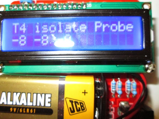

Leave the capacitor connected, you will see the value pulsate on the bottom line of the display as it is calibrating (Mine read 91nF). It will keep pulsating the value until the test concludes (it can take about 2 mins?). When the test finishes it will exit the calibration mode as indicated on the display, reverting to testing the Capacitor and indicating the value being tested as below:
(Sorry about the breadcrumbs on the bench, this is how one works when into resolving problems)

The unit then times out after about 30 secs and switches off.
Now if you have gone about this procedure correctly, when you next turn on the unit it will no longer display the 35pF offset as shown at the start of this blog, the display will show the following after the initial Volts check and sign on etc:

You are now ready to start testing your components. Which we will come to in Part 3.
Notes:
Shortly after I proved my theory about the elimination of the 35pF offset, I contacted VK3YE via email. Peter came straight back with a BIG thank you, after he too had tried my method out, and it had worked on his unit first time! The only problem he had found, he couldn't then test small value capacitors? Eg: 47 pF measured fine (48pF) but 22pF was not recognised? Hmmm!
I spent my teatime reading the manual again, and found it!:
Part of the introduction in the German manual states:
Chapter 1
Features
10: One capacitor can be detected and measured. It is shown with symbol and
value. The
value can be from 35pF (8MHz clock, 70pF @1MHz clock) to 40mF with a
resolution of up to
1 pF (@8MHz clock].
----------------------
So nothing below 35pF will work. Or will it?
Peter mentioned in the last part of his email:
Still you can get around this by making a small jig with (say) 100pF for
use with small capacitors and just deduct 100pF.
Wednesday, 11 February 2015
Building the M328 component tester (1)
Having being inspired by one of Peter VK3YE recent video's, it was time to purchase a couple of kits and dust the soldering iron off the shelf and get down to building one:
This could prove to be a very useful piece of component test kit, for the constructor and repair bench, including the novice. It does, R, L, C including ESR, Diodes and Transistors, giving the pin configuration detail of the Semiconductor device undertest as well as the useful gain figures.

It is basically a copy of the Karl-Heinz Kubbeler design, centred around a programmable ATMEGA328 microcontroller which is very well documented. The kit took about 2 weeks to arrive from China, which contains a well made PCB, display module and all the components, including the blown main chip all for around £8.00 ($12 US). It comes with no instructions on how to put it together, but a Chinese manual is downloadable from the purchase site, which I will make a link available at the bottom of this Blog. Infact, really you don't need the manual for construction, as the component values are printed on the PCB, it just helps a little to get one or two things installed the right way around like the switch, and the circuit diagram can be useful for component reference and maybe fault finding later? Of course the Chinese manual is written in Chinglish, we are refered to welding not soldering! I don't think my old arc welder would prove very suitable for this project somehow? Hi!

I emptied all the components out of their anti-static packet into an empty biscuit tin, so I didn't lose any of them. I was away, it took around 2 hours of soldering, and sorting out the correct values, a DMM can help with the resistors values, as I found an orange band can look like a red, so its best to measure them to avoid confusion and getting one soldered in the wrong position. Transistors are marked to board values, and the marking of the outline makes sure you cannot put the devices in the wrong way around.
At this stage it is time to check the board over for shorts, man made solder links etc, and snip off component ends. All looked ok, time to connect the 9V battery, before inserting the main ATMEGA IC, at this point a DMM is required to check for regulated 5V at the IC socket pins 7 & 22, all confirmed correct and the regulator was doing its job!
All in all it was quite a relaxing project to put together, I didn't find anything too difficult, although a bit of care is needed aligning up the pins of the main chip before pushing firmly home into its socket.

There is not much work to do with the display board as most of this is already constructed, just a strip of header pins that carefully require soldering in across the top of its PCB. This then mates up with the socket strip on the main board when it is pushed home and bolted together.
All looked good time to switch on! If it fires up correctly one push of the On button should turn on the display. In my case it did, and didn't? When I released the Push To Make switch, it went out ? Some folk have had problems putting the switch in the wrong way around, I knew I hadn't done this and a quick check confirmed the switch had been inserted correctly, time to investigate further? The clue was the LED under the display board wasn't on, a quick check with the DMM around the circuit in this area confirmed my thoughts, I had put the LED in the wrong way, huh! Oh dear! I had to pull it all apart, split the two boards desolder and turn the LED around, and then put it all back together.

Great it then fired up correctly, and held in its On state after pushing and releasing the button, a quick adjustment of the contrast pot to get the display correct and all was looking well, time to calibrate..
To be continued in part 2.
References:
This is where I purchased the kit from, although they are available from ebay too:
http://www.banggood.com/DIY-Meter-Tester-Kit-For-Capacitance-ESR-Inductance-Resistor-NPN-PNP-p-929603.html
Construction manual:
https://www.dropbox.com/s/zpjwo3vfv9yfr5b/SKU136841%20M8install.pdf
Design manual helps with Calibration and other stuff:
www.mikrocontroller.net/attachment/143813/TTester_096k.pdf
Newer version of manual:
www.mikrocontroller.net/attachment/164956/ttester_eng104k.pdf
This could prove to be a very useful piece of component test kit, for the constructor and repair bench, including the novice. It does, R, L, C including ESR, Diodes and Transistors, giving the pin configuration detail of the Semiconductor device undertest as well as the useful gain figures.
It is basically a copy of the Karl-Heinz Kubbeler design, centred around a programmable ATMEGA328 microcontroller which is very well documented. The kit took about 2 weeks to arrive from China, which contains a well made PCB, display module and all the components, including the blown main chip all for around £8.00 ($12 US). It comes with no instructions on how to put it together, but a Chinese manual is downloadable from the purchase site, which I will make a link available at the bottom of this Blog. Infact, really you don't need the manual for construction, as the component values are printed on the PCB, it just helps a little to get one or two things installed the right way around like the switch, and the circuit diagram can be useful for component reference and maybe fault finding later? Of course the Chinese manual is written in Chinglish, we are refered to welding not soldering! I don't think my old arc welder would prove very suitable for this project somehow? Hi!
I emptied all the components out of their anti-static packet into an empty biscuit tin, so I didn't lose any of them. I was away, it took around 2 hours of soldering, and sorting out the correct values, a DMM can help with the resistors values, as I found an orange band can look like a red, so its best to measure them to avoid confusion and getting one soldered in the wrong position. Transistors are marked to board values, and the marking of the outline makes sure you cannot put the devices in the wrong way around.
At this stage it is time to check the board over for shorts, man made solder links etc, and snip off component ends. All looked ok, time to connect the 9V battery, before inserting the main ATMEGA IC, at this point a DMM is required to check for regulated 5V at the IC socket pins 7 & 22, all confirmed correct and the regulator was doing its job!
All in all it was quite a relaxing project to put together, I didn't find anything too difficult, although a bit of care is needed aligning up the pins of the main chip before pushing firmly home into its socket.
There is not much work to do with the display board as most of this is already constructed, just a strip of header pins that carefully require soldering in across the top of its PCB. This then mates up with the socket strip on the main board when it is pushed home and bolted together.
All looked good time to switch on! If it fires up correctly one push of the On button should turn on the display. In my case it did, and didn't? When I released the Push To Make switch, it went out ? Some folk have had problems putting the switch in the wrong way around, I knew I hadn't done this and a quick check confirmed the switch had been inserted correctly, time to investigate further? The clue was the LED under the display board wasn't on, a quick check with the DMM around the circuit in this area confirmed my thoughts, I had put the LED in the wrong way, huh! Oh dear! I had to pull it all apart, split the two boards desolder and turn the LED around, and then put it all back together.
Great it then fired up correctly, and held in its On state after pushing and releasing the button, a quick adjustment of the contrast pot to get the display correct and all was looking well, time to calibrate..
To be continued in part 2.
References:
This is where I purchased the kit from, although they are available from ebay too:
http://www.banggood.com/DIY-Meter-Tester-Kit-For-Capacitance-ESR-Inductance-Resistor-NPN-PNP-p-929603.html
Construction manual:
https://www.dropbox.com/s/zpjwo3vfv9yfr5b/SKU136841%20M8install.pdf
Design manual helps with Calibration and other stuff:
www.mikrocontroller.net/attachment/143813/TTester_096k.pdf
Newer version of manual:
www.mikrocontroller.net/attachment/164956/ttester_eng104k.pdf
Subscribe to:
Posts (Atom)