Grid Watch UK

Showing posts with label kit. Show all posts

Wednesday, 12 December 2018

One for the Boys or maybe the Girls

When I started in this hobby when I was around 7, it was batteries and old car bulbs nicked from my Dad's shed, with wires held on the terminals with sellotape, that was to give me my first taste of electronics, well before I even started making crystal sets. This is all what is needed, just a little nudge of encouragement to spark enthusiasm in our hobby. Little did I know then, I would have held a job in the industry and have an Amateur Radio licence to my name and I would be writing about it today.


So I was in my local discount store the other day, something caught the corner of my eye, an electronic kit. Tronex 50+ Circuit Lab. Made in, you guess right China! But does similar to what I have mentioned above. Yes it resembles the kits that were once produced in late 70's, where wires were held under springs to connect each component into the circuit.


Only having two daughters, one whom is now married, and the other that is now in her latter years of High school, a chance perhaps to encourage her, and get her away from playing with her tablet and computer during the long hours of these dark nights. So I decided to buy one for her Christmas stocking. My wife said you only bought it so you can play with it didn't you? I said no, this is a good educational tool and can be used to encourage, especially with her having to do a science at school.


Not hopeful she will be another Ham in the future, but you never know where it will lead? For overseas readers of my blog I notice there are Tronex kits on ebay of similar content.

I will return to this when she decides to investigate and play, further info here:

https://www.homebargains.co.uk/products/14749-tronex-50-circuit-lab.aspx


Wednesday, 8 April 2015

The Pixie money game!

A couple of months ago my friend and Blogger G3XBM was into buying Pixie kits from China, he thought he had bought a bargain for the £7.00 he paid for the kit?  Shortly afterwards I found the kits at around a couple of Pounds lower than Roger had bought his for. But this was short lived, a week or so later Roger blogged that Andy Cutland had found them for £3.19 pence, this undercut my price yet again by nearly £1.50!!

Well the story continues!! I have now found the Pixie kits cheaper yet again!!! The complete kit as above (inc PCB components and Xtal), all for a penny pinching £2.89p ($4.30 US), and the more you buy the cheaper it gets! Oh yes I forgot the price "Includes" shipping!!

You could buy several kits without busting the bank, and put them on different Bands with Xtal and small mod of low pass filter changes.

Is this now the cheapest Transceiver kit  in the world, or can anyone find them cheaper still??


Saturday, 14 February 2015

Building the M328 component tester (2)


Calibration of the M328

I have previously explained how to go about building the M328 in Part (1)

Now this is where it all gets very interesting!

When I watched the VK3YE  video (A number of times may I add), I had always wondered about the 35pF offset and why Peter couldn't eliminate it? I had read the manual written by Karl-Heinz Kubbeler, upside down and inside out around the area of calibration (Section 3.2). I had felt maybe Peter had missed a step, or maybe two? But it would only be when I finally built the project I would be able to put my theory into action! After all I couldn't just pop over to Melbourne and explain, it is not a couple miles down the road from the UK is it, and doubtful some nut with a theory would be welcome asking for a phone number anyway??


Before you start calibration you will need to make yourself a three pronged shorting link, and a get hold of  a 100nF (0.1uF) Capacitor. The value can be greater, but not less than 100nF, which will be required for the final part of the Cal procedure:


You then insert the link into all three terminals (1,2,3) on the bottom terminal block, make sure the connection is tight. Press the On button this will put the unit into Self Test Mode:


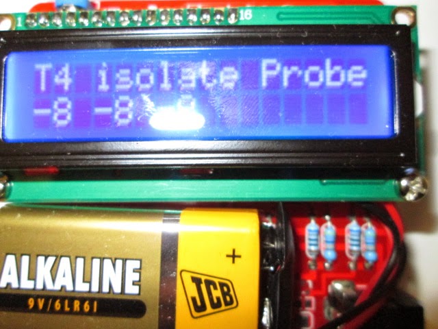
When it gets to "T4 Isolate Probe" which I assume means Test 4? Remove the Link smartly! Do NOT touch any parts of the unit as it resumes its test and calibration cycle:


Let it move on, until it gets to the last screen which at this point you will require the 100nF Capacitor and Insert it between Terminals 1 & 3:


Leave the capacitor connected, you will see the value pulsate on the bottom line of the display as it is calibrating (Mine read 91nF). It will keep pulsating the value until the test concludes (it can take about 2 mins?). When the test finishes it will exit the calibration mode as indicated on the display, reverting to testing the Capacitor and indicating the value being tested as below:

(Sorry about the breadcrumbs on the bench, this is how one works when into resolving problems)


The unit then times out after about 30 secs and switches off.

Now if you have gone about this procedure correctly, when you next turn on the unit it will no longer display the 35pF offset as shown at the start of this blog,  the display will show the following after the initial Volts check and sign on etc:


You are now ready to start testing your components. Which we will come to in Part 3.

Notes:

Shortly after I proved my theory about the elimination of the 35pF offset, I contacted VK3YE via email. Peter came straight back with a BIG thank you, after he too had tried my method out, and it had worked on his unit first time! The only problem he had found, he couldn't then test small value capacitors? Eg: 47 pF measured fine (48pF) but 22pF was not recognised? Hmmm!

I spent my teatime reading the manual again, and found it!:


Part of the introduction in the German manual states:
Chapter 1
Features
10: One capacitor can be detected and measured. It is shown with symbol and value. The
value can be from 35pF (8MHz clock, 70pF @1MHz clock) to 40mF with a resolution of up to
1 pF (@8MHz clock].
----------------------
So nothing below 35pF will work. Or will it?

Peter mentioned in the last part of his email:

Still you can get around this by making a small jig with (say) 100pF for use with small capacitors and just deduct 100pF. 


Wednesday, 11 February 2015

Building the M328 component tester (1)

Having being inspired by one of Peter VK3YE recent video's, it was time to purchase a couple of kits and dust the soldering iron off the shelf and get down to building one:

This could prove to be a very useful piece of component test kit, for the constructor and repair bench, including the novice. It does, R, L, C  including ESR, Diodes and Transistors, giving the pin configuration detail of the Semiconductor device undertest as well as the useful gain figures. 


It is basically a copy of the Karl-Heinz Kubbeler design, centred around a programmable ATMEGA328 microcontroller which is very well documented. The kit took about 2 weeks to arrive from China, which contains a well made PCB, display module and all the components, including the blown main chip all for around £8.00 ($12 US). It comes with no instructions on how to put it together, but a Chinese manual is downloadable from the purchase site, which I will make a link available at the bottom of this Blog. Infact, really you don't need the manual for construction, as the component values are printed on the PCB, it just helps a little to get one or two things installed the right way around like the switch, and the circuit diagram can be useful for component reference and maybe fault finding later? Of course the Chinese manual is written in Chinglish, we are refered to welding not soldering! I don't think my old arc welder would prove very suitable for this project somehow? Hi!


I emptied all the components out of their anti-static packet into an empty biscuit tin, so I didn't lose any of them. I was away, it took around 2 hours of soldering, and sorting out the correct values, a DMM can help with the resistors values, as I found an orange band can look like a red, so its best to measure them to avoid confusion and getting one soldered in the wrong position. Transistors are marked to board values, and the marking of the outline makes sure you cannot put the devices in the wrong way around.

At this stage it is time to check the board over for shorts, man made solder links etc, and snip off component ends. All looked ok, time to connect the 9V battery, before inserting the main ATMEGA IC, at this point a DMM is required to check for regulated 5V at the IC socket pins 7 & 22, all confirmed correct and the regulator was doing its job!  
 
All in all it was quite a relaxing project to put together, I didn't find anything too difficult, although a bit of care is needed aligning up the pins of the main chip before pushing firmly home into its socket.


There is not much work to do with the display board as most of this is already constructed, just a strip of header pins that carefully require soldering in across the top of its PCB. This then mates up with the socket strip on the main board when it is pushed home and bolted together.


All looked good time to switch on! If it fires up correctly one push of the On button should turn on the display. In my case it did, and didn't? When I released the Push To Make switch, it went out ? Some folk have had problems putting the switch in the wrong way around, I knew I hadn't done this and a quick check confirmed the switch had been inserted correctly, time to investigate further? The clue was the LED under the display board wasn't on, a quick check with the DMM around the circuit in this area confirmed my thoughts, I had put the LED in the wrong way, huh! Oh dear! I had to pull it all apart, split the two boards desolder and turn the LED around, and then put it all back together.


Great it then fired up correctly, and held in its On state after pushing and releasing the button, a quick adjustment of the contrast pot to get the display correct and all was looking well, time to calibrate..

To be continued in part 2.

References:

This is where I purchased the kit from, although they are available from ebay too:

http://www.banggood.com/DIY-Meter-Tester-Kit-For-Capacitance-ESR-Inductance-Resistor-NPN-PNP-p-929603.html  

Construction manual:

https://www.dropbox.com/s/zpjwo3vfv9yfr5b/SKU136841%20M8install.pdf


Design manual helps with Calibration and other stuff:

www.mikrocontroller.net/attachment/143813/TTester_096k.pdf

Newer version of manual:

www.mikrocontroller.net/attachment/164956/ttester_eng104k.pdf